DC Motor Control using the L298N Motor Driver Interfaced with the STM32F407 Discovery Kit


Introduction
Hello !! 😄 It's been a long time. Today we will be looking at DC Motor Control using the STM32F407 Development Kit programmed with register-level code (as usual 😁). Motor Control is an integral part of many robotics applications nowadays because the speed and direction of such motors can be easily controlled with the help of PWM pulses applied to the motor that is connected in an H-bridge configuration. This makes it a trouble-free task to integrate such motors into a project. In this tutorial, we will be looking at the L298N Motor Driver Module, which offers a dual H-bridge connection in the IC that allows us to connect and control two motors at once. For the purposes of this demonstration, we will be using a single 12V - 300 RPM DC motor.
Working Principle
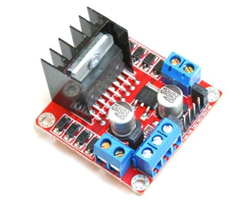
- L298N Motor Driver
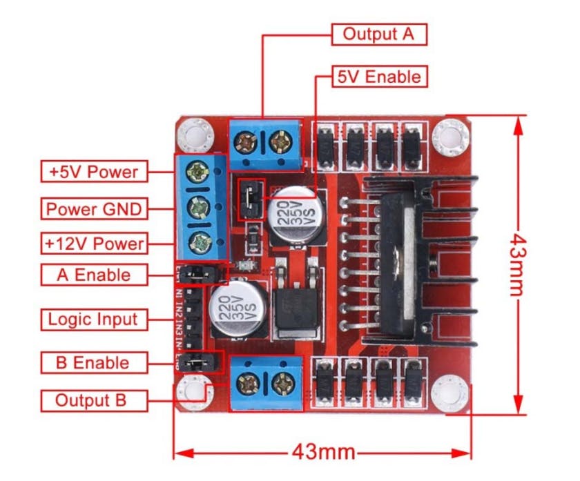
The motor driver has 4 Logic Input pins named IN1, IN2, IN3, and IN4, which are used to control the direction and speed of the motor using a micro-controller. IN1 and IN2 are the inputs for Output A as per the above image. Similarly Output B can be controlled through IN3 and IN4.

The H-bridge has 4 switches, which when closed in specific pairs can be used for changing the direction of the motor. When S1 and S4 are closed, the motor rotates in a particular direction, whereas when S2 and S3 are closed the motor will rotate in the opposite direction as compared to the previous rotation. This is the basic underlying principle that helps in changing the direction of rotation. In terms of the motor driver module, the inputs IN1, and IN2 are connected to each pair of switches described above. To exemplify, IN1 can be connected to both S1 and S4, which when raised to a HIGH level, both the switches close making the motor rotate in a particular direction. This operation is achieved using transistors that switch ON when a positive input is applied to their base. A similar connection pattern can be applied between IN2 and S2 and S3, which is further extended for the inputs IN3 and IN4.
- DC Motor
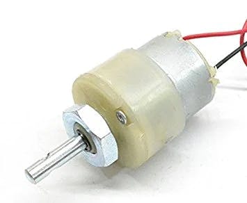
The motor shown above is the one used for this project. It is a 12V-300 RPM DC motor. The speed of the motor can be controlled by varying the DC voltage applied to it. Variable voltage can be implemented by using PWM pulses, which change the voltage based on the Duty Cycle.
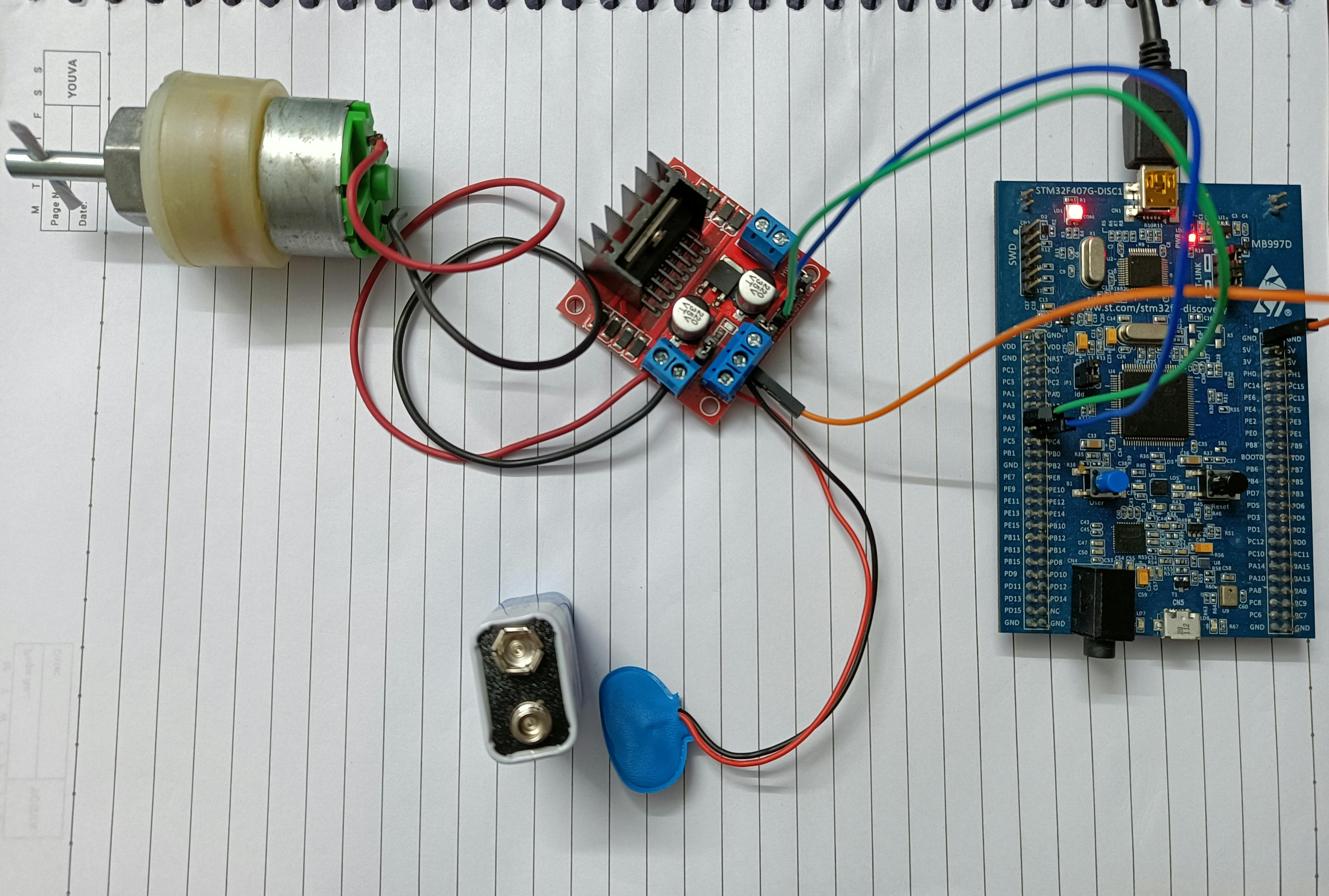
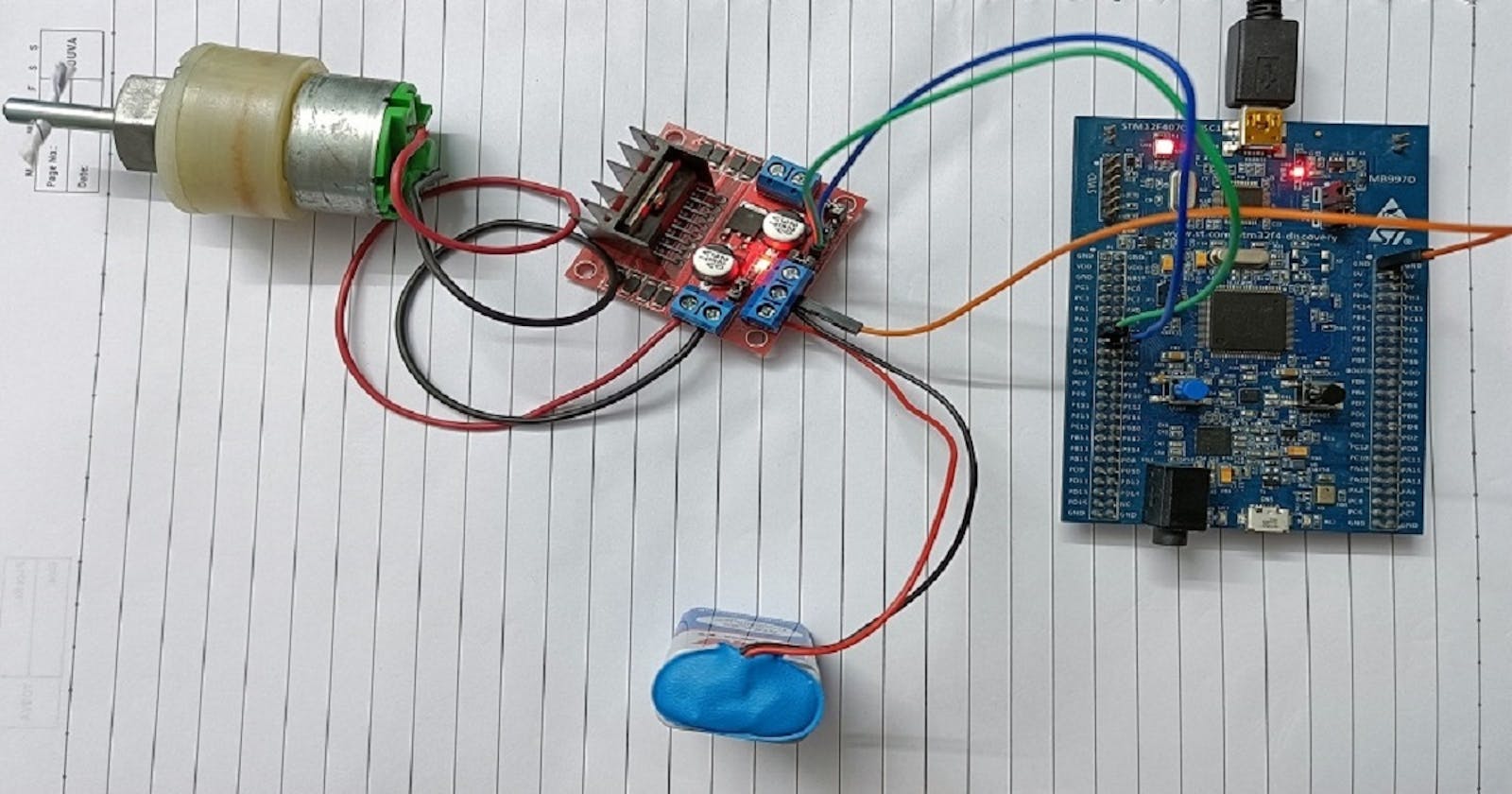
That is all there is to the theoretical part as far as this project is concerned. The connections that need to be made can be found on my Github repository which can be accessed by clicking here.
Components Required
12V-300RPM DC Motor
L298N Motor Driver Module
9V Battery and Connector
STM32F4 based micro-controller
A few jumper wires
Now that we have outlined the components required, let's move on to programming our micro-controller.
Programming the MCU
Let's get into it.
1. Including the necessary Header Files and some comments about the code
/******************************************************************************
 * @file      main.c
 * @author    Ruturaj A. Nanoti
 * @brief     The following code can be used for DC motor control by utilizing
 *            the L298N 2A Motor Driver Module.
 *            The Connections are as follows:
 *            PA5 (Connected to Channel 1 of TIM2) - IN1
 *            PA6 (Connected to Channel 1 of TIM3) - IN2
 *
 *            The motor runs at it's full speed of 300 RPM, at 12V. Since, for
 *            this project the motor is supplied with a 9V battery, the max.
 *            speed for the motor will be 225 RPM. (9V * 300 RPM / 12 V)
 *
 * @date      2022-01-22 (yyyy-mm-dd)
 *****************************************************************************/

// Including the Header Files
#include "stm32f4xx.h"
#define ARM_MATH_M4
These are the header files included at the top of our main.c file. The stm32f4xx.h is the one for our microcontroller and the ARM_MATH_CM4 is for any math operations that we perform in our code.
2. Declaring the User-Defined Functions
// Declaration For User-Defined Functions
void GPIO_Init(void);
void TIM2_Init(void);
void TIM3_Init(void);
void Motor_Control(uint8_t direction, uint16_t speed);
void TIM4_ms_Delay(uint16_t delay);
The void GPIO_Init(void) function is used for configuring all the GPIO pins that are used to interface the L298N Motor Driver with our MCU. void TIM2_Init(void) and void TIM3_Init(void) are used for generating the PWM pulses that will control the speed of our motor. The output of the two timers is connected to IN1 and IN2 respectively. The reason for using two timers is that when IN1 is given a PWM pulse, IN2 needs to stay low. I will be explaining this in detail, in the upcoming sections of the blog. The function void Motor_Control(uint8_t direction, uint16_t speed) is used for controlling the motor's speed and direction, and it takes in two parameters which are direction and speed. Finally, we have, void TIM4_ms_Delay(uint16_t delay) that is used to provide a delay in milliseconds between certain instructions in the code.
3. Defining the User-Defined Functions
- The
GPIO_Init()function,
// Definitions for User-Defined Functions
void GPIO_Init(){
// Enable the Clock for GPIOA
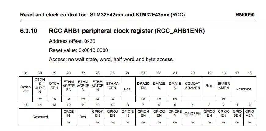
RCC->AHB1ENR |= RCC_AHB1ENR_GPIOAEN;
// Set PA5 and PA6 in alternate function mode
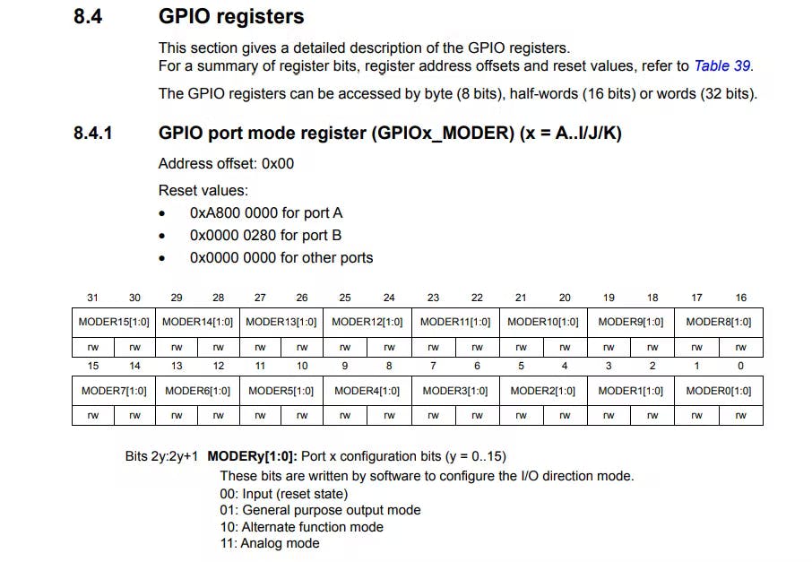
GPIOA->MODER |= ( GPIO_MODER_MODER5_1 | GPIO_MODER_MODER6_1 );
// Configuring PA5 and PA6 as pull down
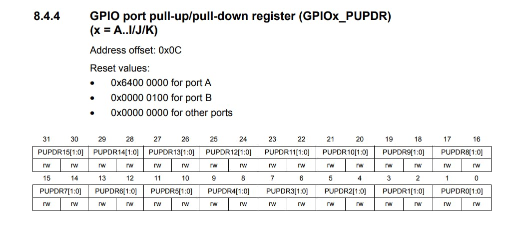
GPIOA->PUPDR |= ( GPIO_PUPDR_PUPDR5_1 | GPIO_PUPDR_PUPDR6_1 );
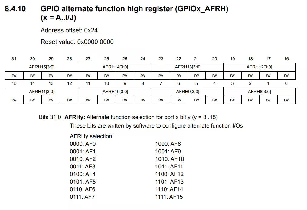
// Select AF1 for PA5 and AF2 for PA6
GPIOA->AFR[0] |= ( GPIO_AFRL_AFRL5_0 | GPIO_AFRL_AFRL6_1 );
}
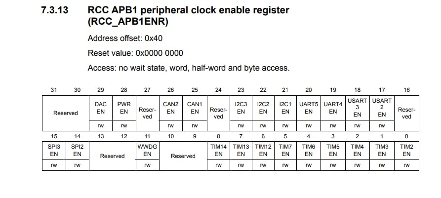
Firstly, the GPIOA clock is enabled by writing a 1 to the GPIOAEN bit in the RCC->AHB1ENR register.
After that, PA5 and PA6 need to be configured in Alternate Function mode. This is done by writing 10 to the MODER5[1:0] and MODER6[1:0] bits in the GPIOA->MODER register.
Then, PA5 and PA6 are set to Pull Down mode by writing 10 to the PUPDR5[1:0] and PUPDR[1:0] bits in the GPIOA->PUPDR register.
Finally, we need to set the AF mode for PA5 and PA6, for this we choose AF1 and AF2 respectively since TIM2 corresponds to AF1 and TIM3 corresponds to AF2. This is done by writing a 1 and a 10 to the AFRL5[3:0] and AFRL6[3:] bits in the GPIOA->AFR[0] register.
- Now let's look at
TIM2_Init()function,
void TIM2_Init(){
RCC->APB1ENR |= RCC_APB1ENR_TIM2EN;
TIM2->PSC = 16-1; //Setting the clock frequency to 1MHz.
TIM2->ARR = 20000; // Total period of the timer = 20ms
TIM2->CNT = 0;
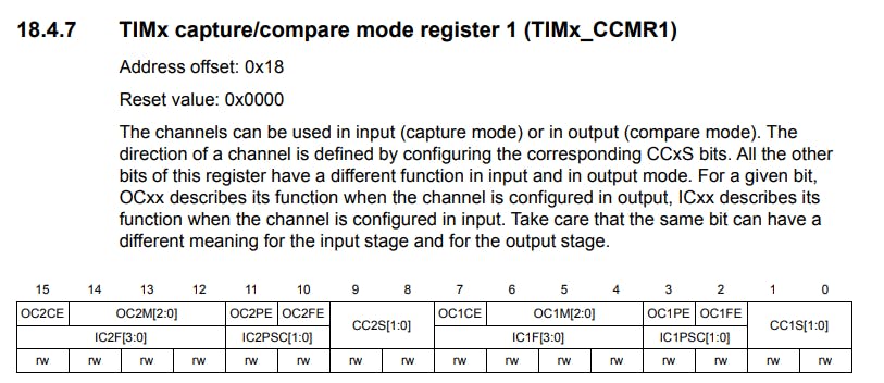
TIM2->CCMR1 = 0x0060; //PWM mode for the timer
TIM2->CCER |= 1; //Enable channel 1 as output
TIM2->CCR1 = 5000; // Pulse width for PWM
}
Here, we start by enabling the clock for the Timer 2, because we will be using it to generate our pulses. This is done by writing a 1 to the TIM2EN bit of the RCC->APB1ENR register. Then, we set the Pre-scalar to 16-1 to reduce the clock frequency to 1MHz from 16MHz, by writing the value to the TIM2->PSC register. After that, we set the time period of the pulse to be generated by assigning the corresponding value to the TIM2->ARR register, which is 20,000 in this case since we want the time period to be 20ms. Each timer tick corresponds to (1 / (1 MHz)), which is 1 micro-second, and since we require the time period to be 20ms the TIM2->ARR register is loaded with 20x1000 micro-seconds, which is 20 milliseconds. Then, we initialize the TIM2-CNT to zero.
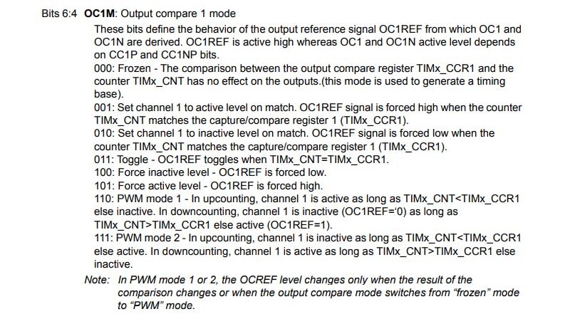
After that, we configure PWM Mode 1 for TImer 2 - Channel 1, and make Channel 1 an output. For that, we first write 0110 to the OC1M bits of the TIM2->CCMR1 register.
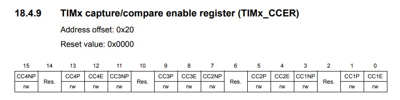
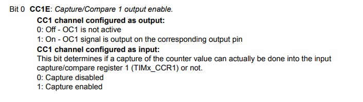
Then, we enable the PWM output on Channel 1 by writing a 1 to the CC1E bit in the TIM2->CCER register.
Finally, we set the initial Pulse-Width to 5000 in the TIM2->CCR1 register.
- Next comes the
TIM3_Init()function,
void TIM3_Init(){
    RCC->APB1ENR |= RCC_APB1ENR_TIM3EN;
    TIM3->PSC = 16-1; //Setting the clock frequency to 1MHz.
    TIM3->ARR = 20000; // Total period of the timer = 20ms
    TIM3->CNT = 0;
    TIM3->CCMR1 = 0x0060; //PWM mode for the timer
    TIM3->CCER |= 1; //Enable channel 1 as output
    TIM3->CCR1 = 5000; // Pulse width for PWM
}
This function is very similar to the function explained above. It aims to achieve the same function. Now let's understand why there's a need for two timers, and why multi-channel PWM output cannot be used for the speed and direction control. For that let's take a look at the H-Bridge configuration again,
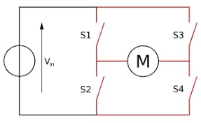
Now, we know that IN1 is connected to one of the pairs of switches in the H-Bridge (the ones we discussed earlier). Suppose that pair is S1 and S4. For changing the direction from the current direction of rotation, we need to open this pair of switches and close the other namely S3 and S4. Notice, that closing all the switches simultaneously will short out the motor, hence such configuration must always be avoided. So, IN1 and IN2 must never be active at the same time. For this situation to be avoided we need to have independent control over the PWM pulses given to IN1 and IN2 which cannot be achieved if we use a single timer with multiple active channels for PWM generation. Since we cannot turn OFF one channel while letting the other run, and hence, the need for two timers.
- Now, comes the
Motor_Control(uint8_t direction, uint16_t speed)function,
void Motor_Control(uint8_t direction, uint16_t speed){
    // direction = 1 => Clockwise Rotations
    // direction = 0 => Clockwise Rotations

    if (direction == 0){
        /* Sending PWM to IN1 and switching off input to IN2 */

        // Waiting for the pulse to finish, if any
        while (TIM3->CNT <= TIM3->CCR1 ){};

        // Then switching off Timer 3
        TIM3->CR1 &= ~TIM_CR1_CEN;

        // Adding a Delay of 1ms
        TIM4_ms_Delay(1);

        // Starting Timer 2
        TIM2->CR1 |= TIM_CR1_CEN;

        // Changing the speed for the motor
        TIM2->CCR1 = (uint16_t)((speed/225.0)*20000);
    }
    else{
        /* Sending PWM to IN2 and switching off input to IN1 */

        // Waiting for the pulse to finish, if any
        while (TIM2->CNT <= TIM2->CCR1 ){};

        // Then switching off Timer 2
        TIM2->CR1 &= ~TIM_CR1_CEN;

        // Adding a Delay of 1ms
        TIM4_ms_Delay(1);

        // Starting Timer 3
        TIM3->CR1 |= TIM_CR1_CEN;

        // Changing the speed for the motor
        TIM3->CCR1 = (uint16_t)((speed/225.0)*20000);
    }
}
This function takes two parameters which are direction and speed. The direction argument is a flag basically that is used to differentiate between clockwise and anti-clockwise direction, and the argument speed is used to get the desired speed. Our 12V-300RPM motor as the name suggests runs at its full speed at 300 RPM with a voltage of 12V, but since we have a 9V Battery the max speed of the motor will be,
$$ Speed_{max} = \frac{9V*300RPM}{12V} = 225 RPM $$
When the function is called, we check the requested direction of rotation using an if-else statement. After that, we check if the pulse is still in the HIGH state before changing the direction, so that the timer is not switched OFF mid-pulse. This is done by waiting until TIM2->CNT is less than or equal to TIM2->CCR1. Then, we switch OFF the corresponding timer and wait for 1 millisecond by writing a 0 to the CEN bit in the corresponding timer's CR1 register, and passing a 1 to the TIM4_ms_Delay() function. After that, we switch ON the desired timer and change the speed to the required value by adjusting the PWM signal accordingly. For this, we first convert the speed into a percentage of the total speed and then multiply it by the value in the ARR register to get the desired pulse width.
$$ PulseWidth = \frac{speed}{225}*ARR $$
Once, this computation is done, the resulting value is updated in the corresponding timer's CCR1 register.
- Then, comes the
void TIM4_ms_Delay(uint32_t delay)function, which handles any time delay requirements that are needed, in themainfunction.
void TIM4_ms_Delay(uint32_t delay){
RCC->APB1ENR |= 1<<2; //Start the clock for the timer peripheral
TIM4->PSC = 16000-1; //Setting the clock frequency to 1kHz.
TIM4->ARR = (delay); // Total period of the timer
TIM4->CNT = 0;
TIM4->CR1 |= 1; //Start the Timer
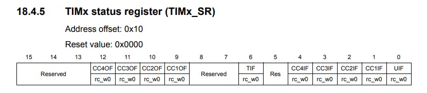
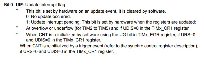
while(!(TIM4->SR & TIM_SR_UIF)){} //Polling the update interrupt flag
TIM4->SR &= ~(0x0001); //Reset the update interrupt flag
}
Most of the configurations done here are very similar to the ones I described above for the function void TIM2_Init(). Here, we enable the clock for the Timer 4, and set the Pre-scalar to 16000-1 to reduce the clock speed to 1 KHz, which means one clock tick corresponds to 1ms. After that, we assign the desired delay value to the TIM4->ARR register, initialize the count to zero and start the timer. Then we poll the UIF or the Update Interrupt Flag, which is set after the desired amount of clock ticks provided in the TIM4->ARR register are done, or in other words when the timer overflows. After the UIF flag is set we clear it from the TIM4->SR register and exit the function.
4. Writing the main function
int main(void){
    GPIO_Init();
    TIM2_Init();
    TIM3_Init();
    TIM2->CR1 |= TIM_CR1_CEN; // Starting Timer 2
    while(1){
        Motor_Control(1, 100);
        TIM4_ms_Delay(10000);
        Motor_Control(0, 170);
        TIM4_ms_Delay(10000);
    }
    return 0;
}
Here, we call all the Initialization functions we defined and start TIM2 by writing a 1 to the CEN bit in the TIM2->CR1 register. After that, we enter an infinite while loop where the Motor_Control(1, 100) function is called with direction flag as 1 and speed as 100. This makes the motor turn clockwise with a speed of 100 RPM. We wait for 10 seconds after this by calling the TIM4_ms_Delay(10000) function with 10000 which represents 10 seconds. Then, we call Motor_Control(0, 170) again, but this time with direction set to 0 and speed set to 170 and similarly wait for 10 seconds.
This whole process continues indefinitely, and the motor keeps changing its speed and direction every 10 seconds.
Conclusion
With that 😃, we have successfully implemented DC motor control using the STM32F407 Development Board.
I hope you enjoyed reading and found this article useful. All the code used here is available on the Github repository which can be accessed by clicking here.
And, the demo video for this blog can be found here.