Generating PWM pulses on the STM32F407 for Servo Motor Control using Bare-Metal Programming


Introduction
Hello!!😃 Today we will discuss controlling a servo motor with PWM pulses, that are generated using the general-purpose timers available on the STM32F407 Discovery kit. As always we will be doing this with Bare-Metal programming. We will be using the PWM mode for the timer to generate the PWM pulse. The Pulse-Width of the pulse will determine the angle or position of the servo motor. The servo motor is used in many applications across various industries since it provides a higher level of control for movement.
Working of the Servo Motor
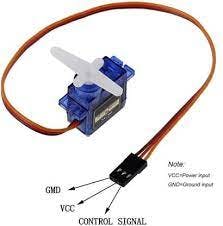
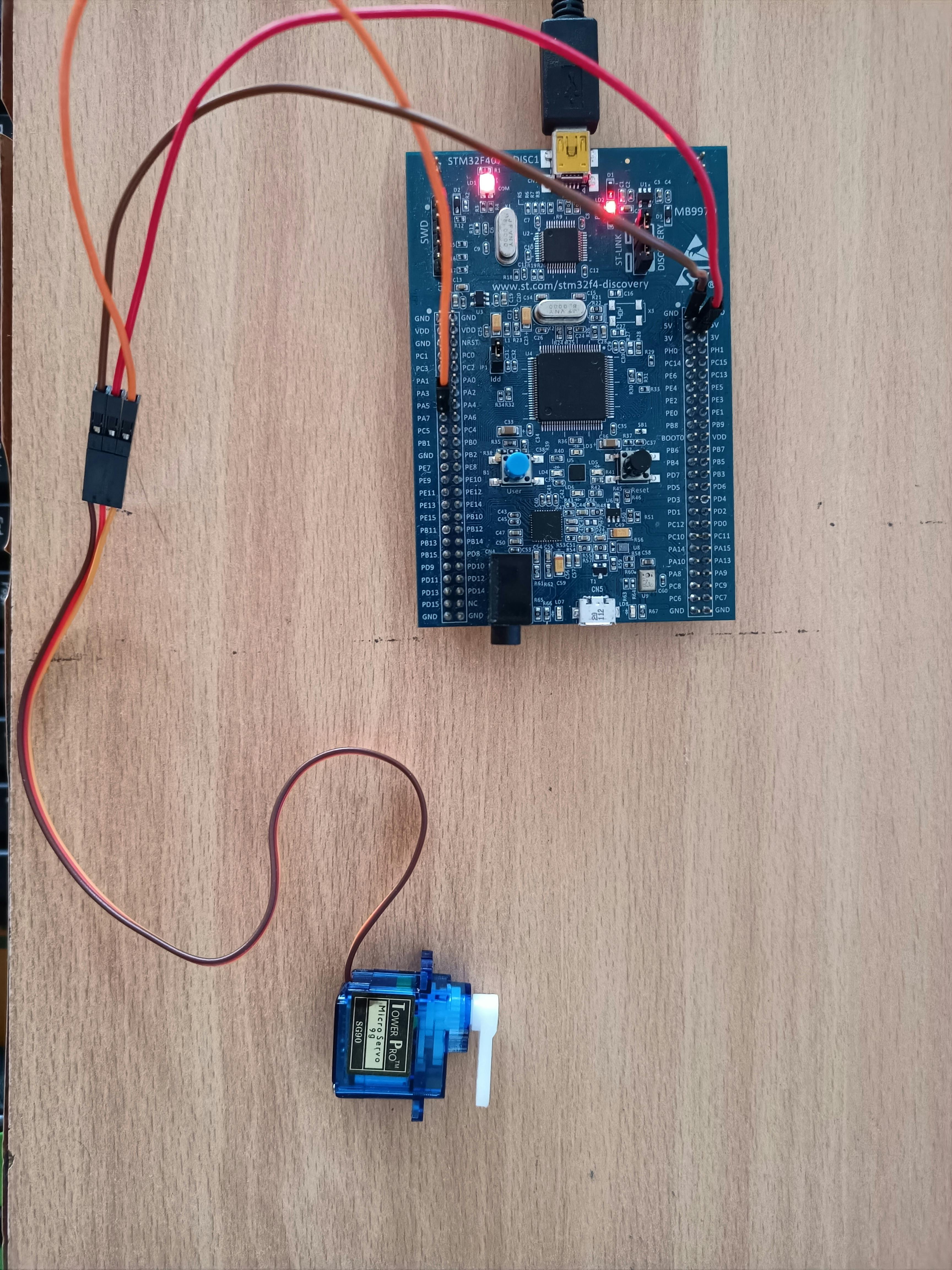
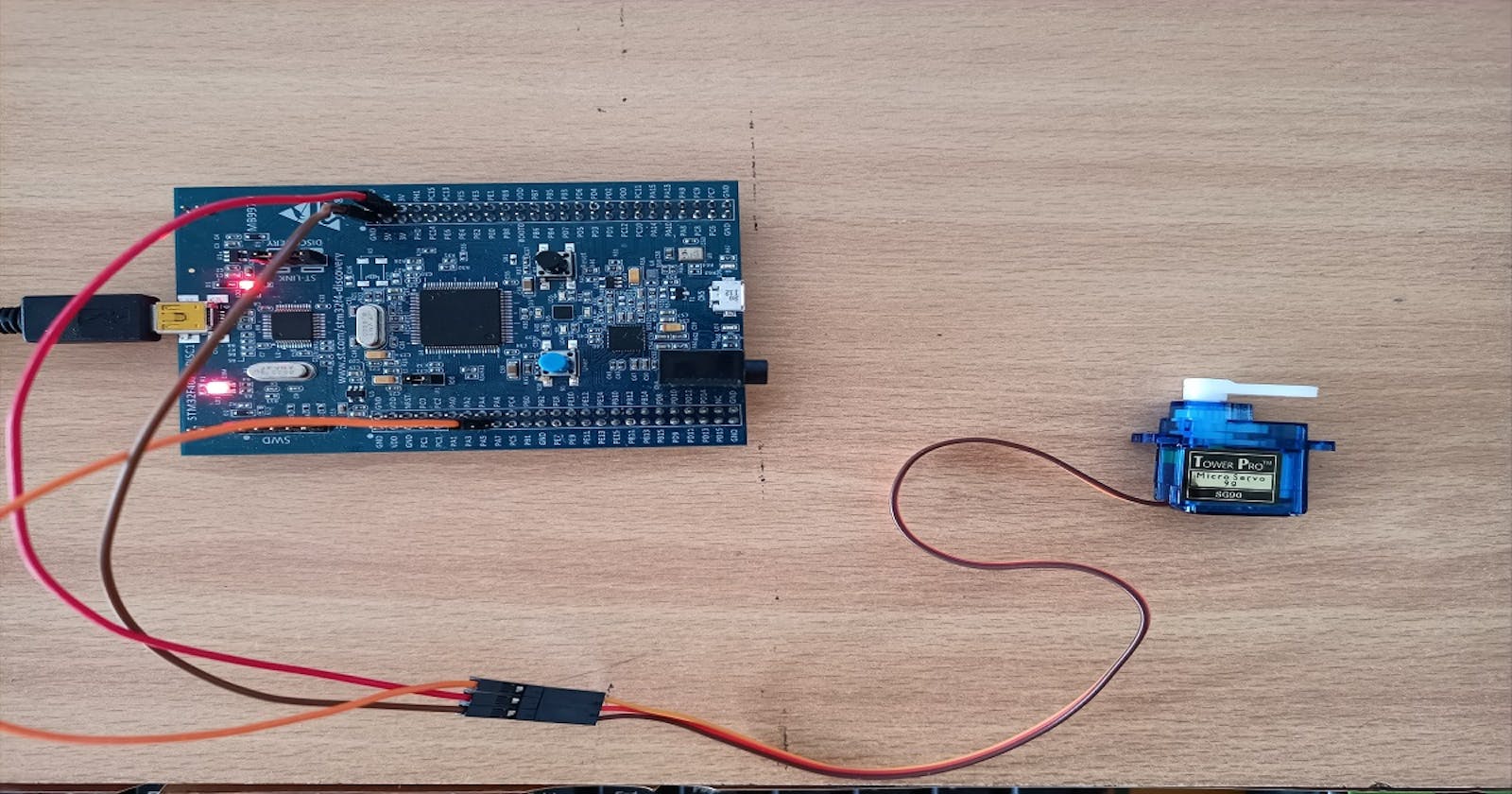
Here, I will be using the sg90 servo motor, which has a 180 degree range of motion. We can control the position of this motor by sending the PWM pulses to the control signal pin, which is shown in the figure above. The VCC and GND are connected to the 5V and GND of the microcontroller respectively. For detailed connections, please visit my GitHub repo, by clicking here.
As seen in the figure below, the time period of the pulse to be generated needs to be 20ms, or in other words, it must have a frequency of 50 Hz. Out of that period, the T on (The time duration for which the state must be HIGH) should be 1ms for moving the motor to the 0 degree position and 2ms for moving the motor to the 180 degrees position.
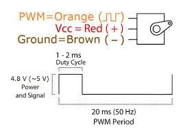
Note: While testing the motor, I could not achieve the full range of its motion by sending pulses with pulse widths between 1ms and 2ms. So, by trial and error, I figured out the actual range of motion can be achieved by sending pulses with pulse-widths between 0.5ms and 2.5ms for the 0 degree and 180 degrees position respectively. This is what I have used in my code as well, as you will see in the latter part of this blog.
Components Required
STM32F4 based microcontroller
A few jumper wires
An sg90 servo motor
And, after gathering the above components, we are ready to start programming our microcontroller.
Programming the MCU
I have used bare-metal programming for the coding, which involves Bitwise AND/OR/XOR operations on the SFRs (Special Function Registers) present on the MCU.
1. Including the necessary Header Files
#include "stm32f4xx.h"
#define ARM_MATH_CM4
These are the header files included at the top of our main.c file. The stm32f4xx.h is the one for our microcontroller and the ARM_MATH_CM4 is for any math operations that we perform in our code.
2. Declaring the User-Defined Functions
void GPIO_Init(void);
void TIM2_Init(void);
void TIM4_ms_Delay(uint32_t delay);
Here, I have declared three functions here and two of them are the void GPIO_Init(void) and void TIM2_Init(void). The former is used to initialize the GPIO pins of the microcontroller that we will be using to interface the servo motor, and the latter is used to initialize and configure Timer 2 to produce the PWM pulses. The third function void TIM4_ms_Delay(uint32_t delay) is used to produce the required delay in milliseconds. It takes in a 32-bit long value for the amount of delay required.
3. Defining the User-Defined Functions
- First, let's look at
void GPIO_Init():
void GPIO_Init(){
RCC->AHB1ENR |= 1; //Enable GPIOA clock
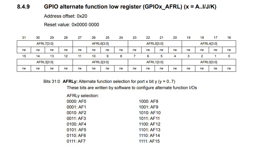
GPIOA->AFR[0] |= 0x00100000; // Select the PA5 pin in alternate function mode
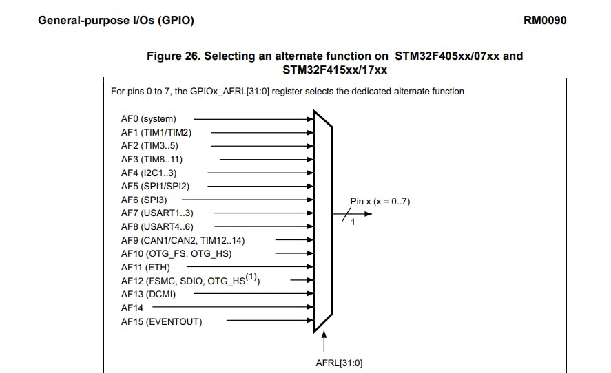
GPIOA->MODER |= 0x00000800; //Set the PA5 pin alternate function
}
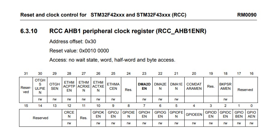
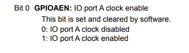
Here, in the first line, we enable the clock for the GPIOA port since the pin PA5 will be used to generate the PWM pulses. We do this by writing a 1 to the GPIOAEN bit of the RCC->AHB1ENR register. Then, we configure PA5 in Alternate Function Mode, because one of its alternate functions is Channel 1 of Timer 2. This is done by writing 10 to the MODER5[1:0] bits of the GPIOA->MODER register, and then writing 0001 to AFRL5[3:0] bits in the GPIOA->AFR[0] register. The pictures describing the registers are given below.
- Now, let's look at
void TIM2_Init(),
void TIM2_Init(){
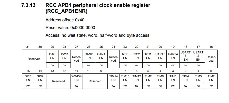
RCC->APB1ENR |=1;
TIM2->PSC = 16-1; //Setting the clock frequency to 1MHz.
TIM2->ARR = 20000; // Total period of the timer
TIM2->CNT = 0;
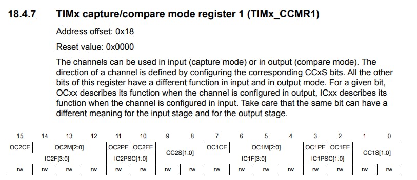
TIM2->CCMR1 = 0x0060; //PWM mode for the timer
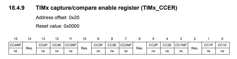
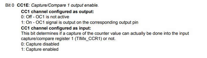
TIM2->CCER |= 1; //Enable channel 1 as output
TIM2->CCR1 = 500; // Pulse width for PWM
}
Here, we start by enabling the clock for the Timer 2, because we will be using it to generate our pulses. This is done by writing a 1 to the TIM2EN bit of the RCC->APB1ENR register. Then, we set the Pre-scalar to 16-1 to reduce the clock frequency to 1MHz from 16MHz, by writing the value to the TIM2->PSC register. After that, we set the time period of the pulse to be generated by assigning the corresponding value to the TIM2->ARR register, which is 20,000 in this case since we want the time period to be 20ms. Each timer tick corresponds to (1 / (1 MHz)), which is 1 micro-second, and since we require the time period to be 20ms the TIM2->ARR register is loaded with 20x1000 micro-seconds, which is 20 milliseconds. Then, we initialize the TIM2-CNT to zero.
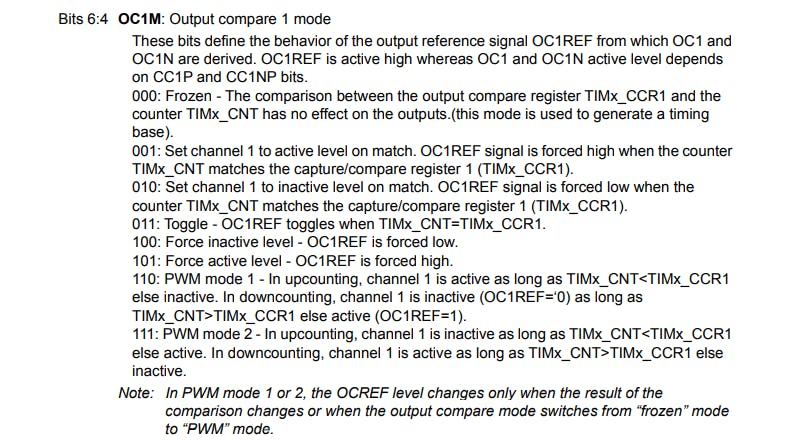
After that, we configure PWM Mode 1 for TImer 2 - Channel 1, and make Channel 1 an output. For that, we first write 0110 to the OC1M bits of the TIM2->CCMR1 register.
Then, we enable the PWM output on Channel 1 by writing a 1 to the CC1E bit in the TIM2->CCER register.
Finally, we set the initial Pulse-Width or initial Angle for the motor, by setting the TIM2->CCR1 register. Here, I have chosen the 0 degree position as the initial position for my servo motor, by assigning a value of 500 or 0.5ms to the TIM2->CCR1 register.
- Then, comes the
void TIM4_ms_Delay(uint32_t delay)function, which handles any time delay requirements that are needed, in themainfunction.
void TIM4_ms_Delay(uint32_t delay){
RCC->APB1ENR |= 1<<2; //Start the clock for the timer peripheral
TIM4->PSC = 16000-1; //Setting the clock frequency to 1kHz.
TIM4->ARR = (delay); // Total period of the timer
TIM4->CNT = 0;
TIM4->CR1 |= 1; //Start the Timer
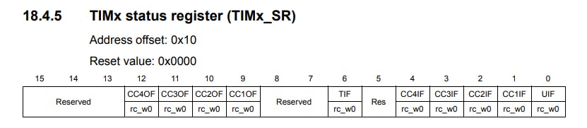
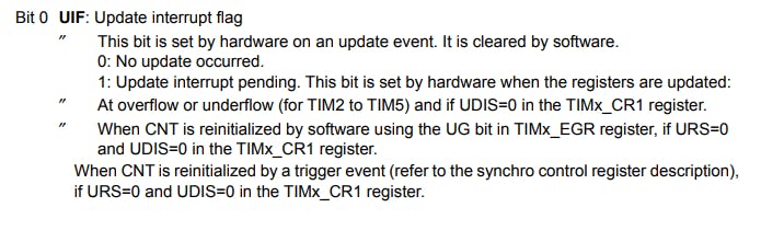
while(!(TIM4->SR & TIM_SR_UIF)){} //Polling the update interrupt flag
TIM4->SR &= ~(0x0001); //Reset the update interrupt flag
}
Most of the configurations done here are very similar to the ones I described above for the function void TIM2_Init(). Here, we enable the clock for the Timer 4, and set the Pre-scalar to 16000-1 to reduce the clock speed to 1 KHz, which means one clock tick corresponds to 1ms. After that, we assign the desired delay value to the TIM4->ARR register, initialize the count to zero and start the timer. Then we poll the UIF or the Update Interrupt Flag, which is set after the desired amount of clock ticks provided in the TIM4->ARR register are done, or in other words when the timer overflows. After the UIF flag is set we clear it from the TIM4->SR register and exit the function.
4. Writing the main function
int main(){
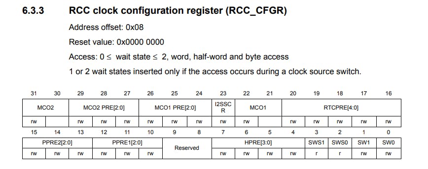
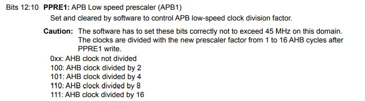
RCC->CFGR |= 0<<10; // set APB1 = 16 MHz
GPIO_Init();
TIM2_Init();
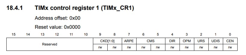
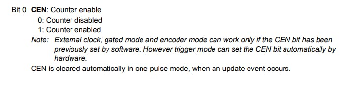
TIM2->CR1 |= 1;
while(1){
if(TIM2->CCR1 < 2500){
TIM2->CCR1 = TIM2->CCR1 + 50;
TIM4_ms_Delay(50);
}
else{
TIM2->CCR1 = 500;
TIM4_ms_Delay(50);
}
}
}
Here, we first set the APB1 clock speed to 16 MHz, by writing a zero to the PPRE[3:0] bits in the RCC->CFGR register, and then we call all the initialization functions we defined above.
Then, we start the Timer 2 by writing a 1 to the CEN bit in the TIM2->CR1 register. By, doing this we start getting the PWM pulses with a pulse width of 0.5ms on PA5.
After that, we enter the infinite while loop, where we first check if the servo motor is at its 180 degrees position. If that is not the case, then we increment the TIM2->CCR1 register by 50, which translates to an angle increment of (50/2500)x180 = 3.6 degrees. After incrementing TIM2->CCR1 we provide a delay of 50ms by calling our TIM4_ms_Delay function. The intention behind giving this delay is to give enough time for the servo motor to acknowledge the change in the pulse-width (which translates to a change in the voltage) and physically move or actuate.
On the other hand, if the motor is at the 180 degrees position, we reinitialize TIM2->CCR1 to 500 or 0.5ms and provide a delay of 50ms.
This whole process keeps on repeating indefinitely, and the motor keeps moving.
Conclusion
😄 With that, we have successfully interfaced a servo motor with our STM32F407 Discovery Kit. There are many other modes available on the General Purpose Timers on the discovery kit. One of them was the PWM mode, which we covered in this blog.
I hope you found this article useful and easy to follow along😀. All the codes used here are present in my GitHub repository, which you can access by clicking here.
And, the demo video for this tutorial can be found here .