Interfacing an Ultrasonic Sensor with the STM32F407 Discovery Board using Bare-Metal Programming


Introduction
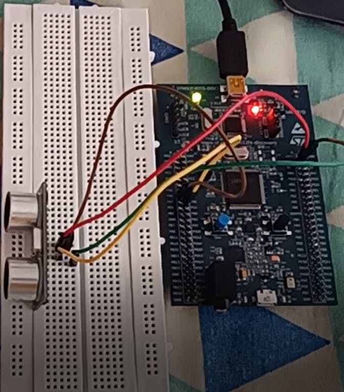
Hello Everyone!! 😃 Today we will be looking at how to interface an ultrasonic sensor, particularly the HC-SR04 with the Cortex-M4 based micro-controller named STM32F407 Discovery board. We will be going about doing this by just manipulating, reading, and writing individual bits of some registers present on the micro-controller known as Special Function Registers (SFRs). Playing with these SFRs is what enables Bare-Metal Programming.
What are SFRs?
Before diving into the code and it's working, let's quickly have a look at what exactly is an "SFR". It is a special register on any micro-controller that enables the programmer to access and control each on-chip peripheral present on the micro-controller like the Timers, ADCs, GPIO ports, etc. Since, the STM32F407 is a 32-bit micro-controller as the name suggests, its SFRs are also 32 bit long, and we can use its peripherals by modifying certain bits in some specific SFRs. All of these modifications will be done by looking at the description provided in the datasheet provided by ST Microelectronics for the STM32F407.
Components Required
Ok, now let's look at all the hardware components that you will require,
An STM32F4 based Micro-controller
An Ultrasonic Sensor ( I have used the HC-SR04)
A few Jumper Wires
A Breadboard
And, that's all you are all set to start working on interfacing the ultrasonic sensor. The connection details are provided in my GitHub repository, whose link i have given at the end of this blog.
The Working Principle of the HC-SR04 Module
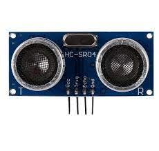
☝️ This is how the ultrasonic sensor module looks like. It has 4 pins, namely the VCC, GND, Trig (Trigger Pin), and the Echo pin. The purpose of this sensor is to calculate the distance between itself and objects placed in front of it. This is achieved by sending 8 bursts of 40KHz signals through the transmitter. After these signals are emitted a timer is started. Now, when these signals encounter an object they reflect back and are detected by the receiver. The time taken by the signal to travel back to the sensor helps determine the distance from the module to the object.
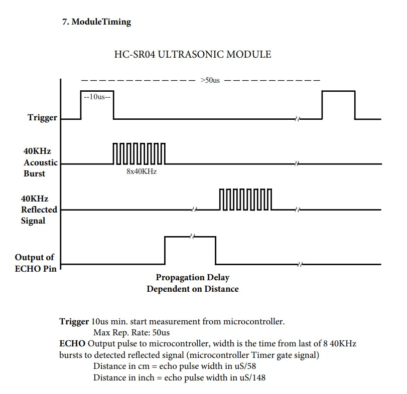
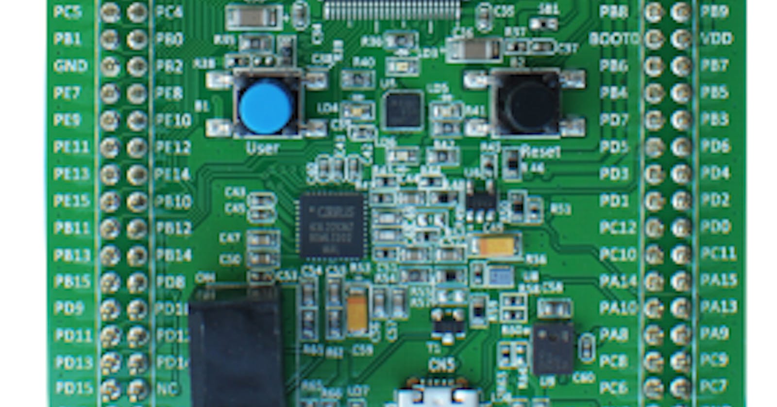
As shown in the above timing diagram, we will need to send a 10-microsecond pulse to the Trig pin of the sensor and detect the pulse width of the pulse sent from the Echo pin of the module. Firstly, to generate a pulse we will set PA5 LOW for some time and then set it to HIGH for the desired duration of the pulse which happens to be 10-microseconds in this case, and then set PA5 to LOW again. Next, to detect the pulse coming in from the Echo pin, we will configure PA6 as an input pin and continuously monitor it for the duration of time it remains HIGH. This will help us detect the pulse and its pulse width.
Mathematical Formulation
Now, these 8 acoustic bursts sent out by the transmitter of the sensor module travel at the rate of 340m/s in air. To calculate the distance we will be using our old simple, Distance = Speed x Time formula. In this formula, the time taken by the receiver to receive the signal back from the object needs to be divided by 2, since the total time includes the time required by the signal to travel both to and back from the object.
Our clock on the STM32F407 runs on a frequency of 16MHz by default. We will use this frequency to determine the time taken by the signal to come back. So, after the signal is emitted each clock cycle of the micro-controller represents 0.0625 micro-seconds which is 1/16MHz. Therefore, the number of clock cycles x 0.0625 micro-seconds will give us the time taken by the receiver to get the signal.
Finally, the distance in cm can be calculated by,
Time = ((Clock Cycles x 0.0625 x 0.000001)/2)
Distance = (340*100)xTime
Since everything needs to be in the same unit, I have converted the time into seconds and distance into centimeters.
Coding the STM32F407 Discovery Board
Most of the operations performed in the code below are either Bitwise OR/AND/XOR Operations or Left and Right Shift Operations, which help us modify individual bits of any register, at any position in the register. These are the operations that help us manipulate the SFRs and hence make up the core of Bare-Metal Programming.
1. Include the necessary Header Files
#include "stm32f4xx.h"
#define ARM_MATH_CM4
These are the basic header files that I have included at the top of my main.c file.
2. Declaring the functions and variables that are used in the code
void GPIO_Init(void);
void TIM2_us_Delay(uint32_t delay); //TIM2 for generating 10us pulse for trig pin

uint32_t data;
double time,dist;
Here, I am using Timer 2 from the 17 on-chip timers available on the STM32F407, which are divided into 16-bit and 32-bit timers. I am using a timer to create an accurate 10-microsecond pulse that is to be sent to the Trig pin of the HC-SR04 to tell the module that the transmission of the 8 acoustic bursts is required.
The GPIO_Init(void) function is used to initialize the GPIO pins required to connect and interact with the sensor, and TIM2_us_Delay(uint32_t delay) is used to create the 10-micro-second pulse. The variables data, time, and dist are declared to represent the clock cycles required for the signal to come back, the calculated time, and the distance.
3. Writing or Defining the User-Defined functions declared above
void GPIO_Init(){
    //Configuring PA5 for generating pulse sent to trig pin
    RCC->AHB1ENR |= 1; //Enable GPIOA clock
    GPIOA->MODER |= 1<<10; //Set the PA5 pin to output mode

    //Configuring output from echo pin to be sent to the board (PA6 pin)
    GPIOA->MODER &= ~(0x00003000); //Set PA6 to input mode
}
Let's talk about the GPIO_Init function first. Here, firstly I enable the clock for GPIOA which is Port A of the GPIO ports, by writing a 1 to the 0th bit of the
RCC->AHB1ENR register. The register and its contents can be seen below,
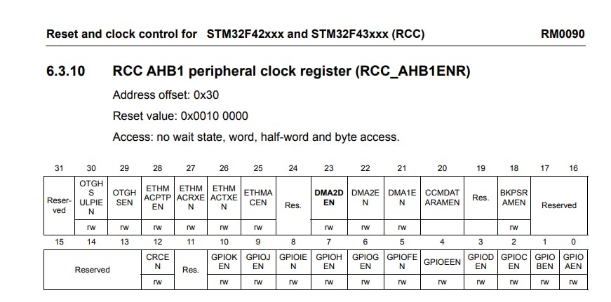
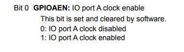
As we can see above, the 0th bit stands for GPIOAEN, which is GPIOA enable. When we write a '1' to it, the clock for GPIO port A is enabled.
Then we move on to the GPIOA->MODER register, with the help of which we can set the PA5 pin in Output Mode because we will need an output pin to send out the 10-microsecond pulse to the sensor module through its Trig Pin. Also, we will set PA6 in Input or Reset Mode, by which we will be able to monitor the Echo Pin of the Ultrasonic Sensor.
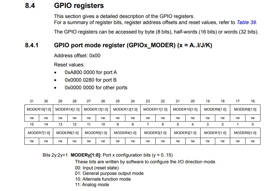
The picture above shows that each pin has 2 bits that control its behaviour. We need PA5 to be in Output Mode, so we write a 01 to MODER5[1:0]. This can be done by just Left-shifting 1 by 10 places, since MODER5[1:0] represents bits 10 and 11. Now, for PA we follow the same procedure, here we need it as an Input, and that state is represented by 00. So we clear out whatever value that might be in MODER6[1:0], by writing GPIOA->MODER &= ~(0x00003000);. This basically takes the current value of the GPIOA->MODER register and bitwise ANDs it with the negation of the value 0x00003000.
Therefore, the pins PA5 and PA6 are now set as Output and Input respectively.
void TIM2_us_Delay(uint32_t delay){
RCC->APB1ENR |=1; //Start the clock for the timer peripheral
TIM2->ARR = (int)(delay/0.0625); // Total period of the timer
TIM2->CNT = 0;
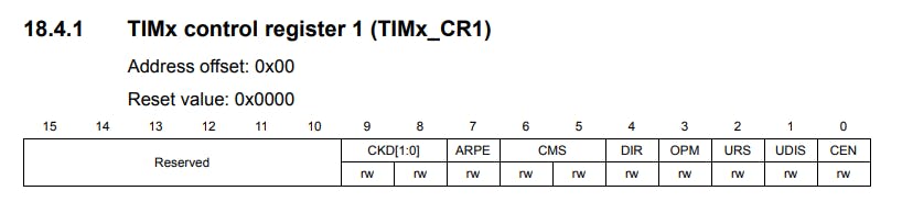
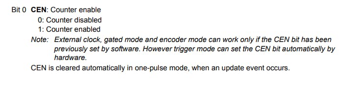
TIM2->CR1 |= 1; //Start the Timer
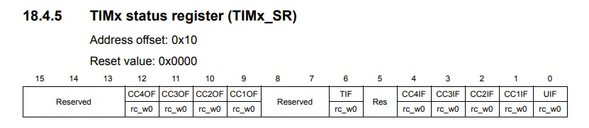
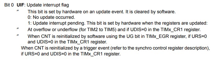
while(!(TIM2->SR & TIM_SR_UIF)){} //Polling the update interrupt flag
TIM2->SR &= ~(0x0001); //Reset the update interrupt flag
}
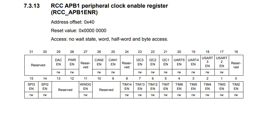
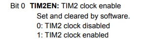
Now, let's take a look at TIM2_us_Delay(uint32_t delay). Here also, first we enable the clock signal for the Timer 2, through the RCC->APB1ENR register.
Then we get the value from the user for the Auto-Reload Register, to generate the desired pulse or time delay in microseconds. To determine the Clock cycles or timer ticks required to generate the desired delay we divide the value given by the user by 0.0625 microseconds and convert the final value into int, since the
TIM2->ARR register only takes int values. Then we set the count value of the timer to zero and start the timer with the lines TIM2->CNT = 0; and TIM2->CR1 |= 1; //Start the Timer respectively. After the timer starts ticking we continuously poll the Status register for the Update Interrupt Flag, to check if it's overflowed with the line while(!(TIM2->SR & TIM_SR_UIF)){} //Polling the update interrupt flag. Once, it's overflowed we come out of the while loop and clear the UIF in the Status Register.
4. Writing the Main Function
int main(){
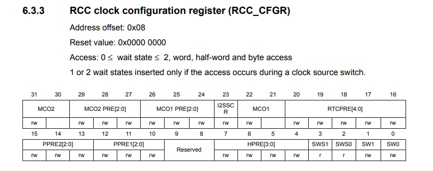
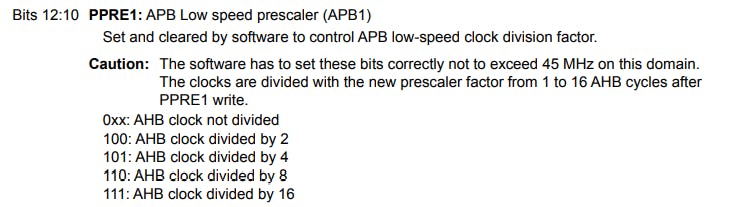
RCC->CFGR |= 0<<10; // set APB1 = 16 MHz
GPIO_Init();
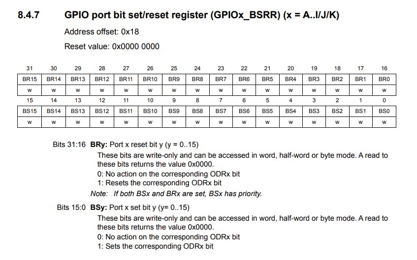
GPIOA->BSRR = 0x00000000;// Setting trig pin to low to initialize the module
while(1){
//1. Sending 10us pulse to
GPIOA->BSRR &= 0x00000000; //PA5 is low
TIM2_us_Delay(2);
GPIOA->BSRR |= 0x00000020;//PA5 set to High
TIM2_us_Delay(10);// wait for 10us
GPIOA->BSRR |= 0x00200000;// Make PA5 low again
//2. Measure the pulse width of the pulse sent from the echo pin by polling IDR for port A
while (GPIOA->IDR & 64){
data = data+1;
}
//3.Converting the gathered data into distance in cm
if (data>0){
time = data*(0.0625*0.000001);
dist = ((time*340)/2)*100;
}
TIM2_us_Delay(4);
data = 0;
}
}
Now let's look at the int main() function in parts. Firstly we set the APB1 clock to 16MHz, by writing a 0 to the 10th bit in RCC->CFGR register with the line RCC->CFGR |= 0<<10; // set APB1 = 16 MHz.
Then we call the GPIO_Init() function to initialize the GPIO pins and set them to low to initialize the module.
GPIO_Init();
GPIOA->BSRR = 0x00000000;// Setting trig pin to low to initialize the module
Now, we enter a while loop since we want to continuously monitor the distance measured by the ultrasonic sensor. This loop is divided into 3 parts:
- First, we send the 10-microsecond pulse to the sensor, so that it can transmit the acoustic bursts. We do this by setting PA5
LOWfor 2-microseconds and then set it toHIGHfor 10-microseconds and then set it toLOWback. This is achieved by using theGPIOA->BSRR register. By doing all this we can create or generate a pulse with a width of 10-microseconds, which will be sent out from PA5.
        //1. Sending 10us pulse to
        GPIOA->BSRR &= 0x00000000; //PA5 is low
        TIM2_us_Delay(2);
        GPIOA->BSRR |= 0x00000020;//PA5 set to High
        TIM2_us_Delay(10);// wait for 10us
        GPIOA->BSRR |= 0x00200000;// Make PA5 low again
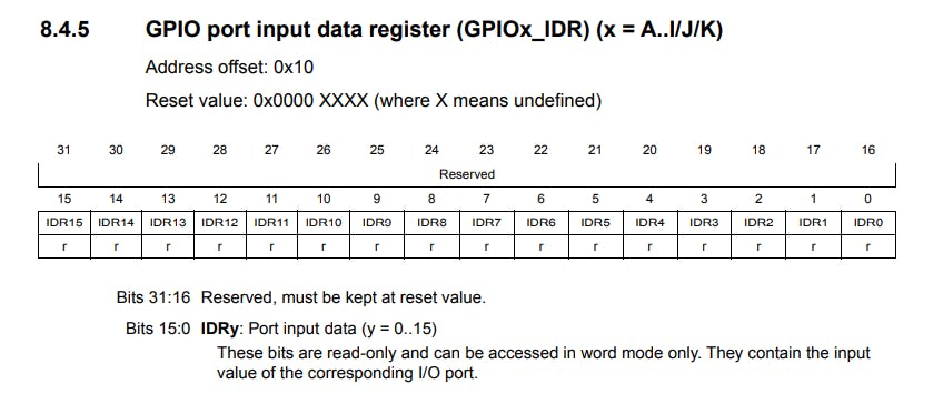
- Then, we continuously monitor the
GPIOA->IDR, which is the Input Data register, and increment the variabledatauntil PA6 isHIGHsince this relates to the pulse sent out by the sensor from the Echo pin, which we are detecting with the micro-controller by monitoring the duration of time for which PA6 isHIGHandLOW. This signifies the number of clock ticks required by the signal to reach the receiver. The value of64is Bitwise ANDed withGPIOA->IDRsince setting itsIDR6bit to1gives the value of64.
        //2. Measure the pulse width of the pulse sent from the echo pin by polling IDR for port A
        while (GPIOA->IDR & 64){
            data = data+1;
        }
- Finally in the last part we perform the necessary calculations discussed in Mathematical Formulation to get our distance in cms. Here, I have only calculated the distance if the value of the
datavariable is greater than zero, this helps increase the efficiency of the code because it reduces the time spent by not calculating the distance if the ultrasonic sensor does not have anything in front of it for a relatively long distance.
        //3.Converting the gathered data into distance in cm
        if (data>0){
            time = data*(0.0625*0.000001);
            dist = ((time*340)/2)*100;
        }
- At the end, we provide a delay of 4-microseconds to enable smooth functioning of the ultrasonic sensor module and set
data=0.
        TIM2_us_Delay(4);
        data = 0;
This whole process in the while loop, keeps on going infinitely, which helps us in getting distance constantly from the sensor.
Conclusion
This marks the end of the tutorial. Hope you enjoyed reading it and were able to easily understand and follow along☺️. Click here to find my GitHub repository containing the entire code, and the datasheet for the HC-SR04 module.
Also, here's a demo video showing the actual working Demo.